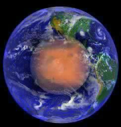
 Cydonia Quest C Geometry C C c Mars Odyssey Reveals New Geometry in the D&M Pyramid Part Three Note: This website is best viewed at a screen resolution of 800 x 600 pixels. Higher resolution settings will reduce both the size and quality of the images displayed, thus leading to a loss of detail. For tips on adjusting screen resolution and other ways of improving the screen appearance of the internet click this "stargate" µµµ. C cccccccccccccccccccccccccccccccccccccc c Introduction This article continues the analysis of the new geometry that was discovered in the D&M Pyramid by the Mars Odyssey spacecraft in early 2002.
|
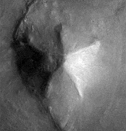
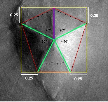
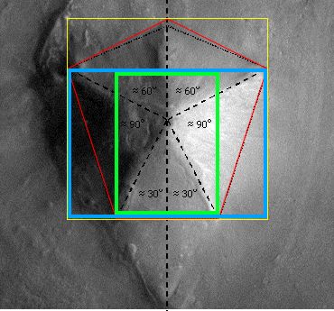
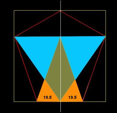
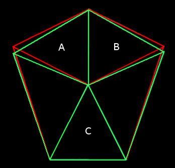
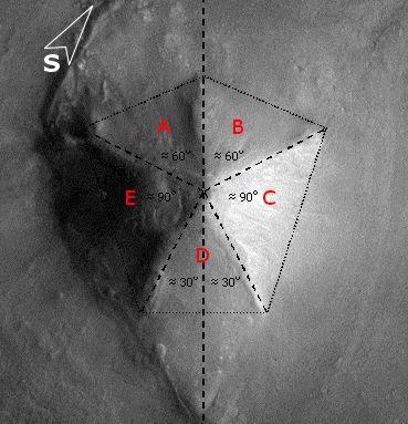
To recapitulate: the Mars Odyssey imagery revealed that the D&M floor plan was primarily based on a southerly pointing pentagon rather than the northerly pointing pentagonal pattern seen in Viking imagery. Although this southerly pointing pentagon is not regular, it is extremely bi-symmetrical, with the two sides of the D&M closely mirroring the other. This aspect is illustrated very well in Mark Carlotto's flip animation above. A second surprise in the Mars Odyssey images is the remains of a triangular platform jutting out from the D&M and following the same pattern of mirror symmetry. For more details readers are referred to Parts 1 & 2 (see µµµ & µµµ). c The D&M's Deeper Geometry The aim of Part 3 is to explore the deeper levels of geometry that seem to be intrinsic to the D&M. If the D&M actually is artificial then it is now heavily damaged by the passage of time. This requires that a "best fit" of its outline and facets has to be estimated from what we can see today. Fortunately, Dr. Carlotto has already done this work, as can be seen on his web page by clicking µµµ. Carlotto's results are shown in Figure 1, which is oriented pointy side up, with south towards the top of the image. This orientation is more useful for further analysis and will be adopted in the rest of this article. C Figure 1 - Mark Carlotto's diagram ccccccccccccccccccccccccccc c Carlotto's outlines have been adopted for this study with one small adjustment. In Figure 1 the tip of the D&M's south-eastern corner is not enclosed in Carlotto's diagram (as confirmed by high resolution MOC imagery in 2004). When the boundary is adjusted for this then we find that the D&M is as wide as it is long. This means that the D&M pentagon can be circumscribed by a square. Moreover, we find that the highest point on the D&M from which each of its five ridge lines begin, corresponds to the exact centre of this circumscribing square. The square is, therefore, as important to the geometry of the D&M as the four sided pyramids of Earth. All these features are shown in Figure 2. C Figure 2 - the D&M circumscribed and centred by a square Ccccccccccccccccccccccccccc C Please note that the diagrams on this page are for figurative purposes only and will not be entirely accurate representations of the hard copy printouts that were used for measurement. This is for two reasons. Firstly, freehand drawing of diagrams with a mouse is difficult. Secondly, the vagaries of horizontal and vertical screen settings on different computer monitors may distort images from their true proportions.
|
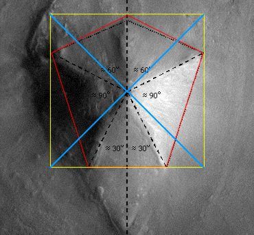
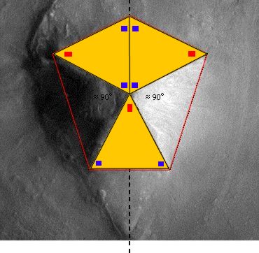
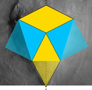
When the positioning of the corners of the D&M are considered in relation to the corners of the square, the relationship shown in Figure 3 is revealed. Four of the D&M corners touch the square at a distance a quarter length from the square's own corners. This means that the four D&M ridge lines (shown in green) that end at these D&M corners must be all the same length. (There is a geometrical reason for this that we will come to later on). C Figure 3 - The D&M proportioned to the square ccccccccccccccccccccccccccc C In Dr. Carlotto's suggested floorplan for the D&M in Figure 1 the divergence angles from the centre for the five facets is two angles of 90 degrees and three of possibly 60 degrees. Measurements of the Carlotto diagram reveal that the divergence angle for facet "D" is smaller than 60 degrees and those for facets "A" and "B" are greater. (The divergence angles in the diagram of 90 degrees for the facets "C" and "E" hold true). One of the effects of the small adjustment made to the Carlotto diagram in this article is that facets "A" and "B" are converted into isosceles triangles. These isosceles triangles turn out to be approximately the same shape and size as facet "D", but oriented to it at a right angle. This is shown in Figure 4 in which internal angles that are approximately the same are coded with the same colour symbol. C Figure 4 - Identical isosceles triangles ccccccccccccccccccccccccccc C When we consider the above diagram an interesting pattern springs into view that makes sense of the triangular platform that mirrors facet "D". Facets "C" and "E" are effectively squares that have been cut diagonally in half. Meanwhile, joining together facets "A" and "B" creates a rhombus with sides of equal length. These rhombus sides are also equal in length to the sides of the squares inherent in facets "C" and "E". If facet "D" is now flipped over onto the adjacent triangular platform this replicates the rhombus made by facets "A" and "B". So, when the triangular platform is included into the D&M geometry we find four geometrically related four sided shapes. This is all illustrated in Figure 5. C Figure 5 - The pattern of 4 sided shapes ccccccccccccccccccccccccccc C A regular pentagon centred at the middle of a square cannot be circumscribed by that square. There are an infinite number of ways in which a pentagon can be distorted to be circumscribed by a square. If the D&M does turn out to be artificial, was there a specific geometrical principle that the designers used to arrive at the pentagonal shape we see today? The most likely geometry that was used is a rectangle with sides in the ratio 4 by 3. A second possibility - which does not fit the D&M's current shape so well - is a scheme based on the cross section of a tetrahedron and the tetrahedral angle of 19.5 degrees. C The 4 x 3 rectangle explanation When the rectangle created by the two lower corners of the circumscribing square and the points higher up where the D&M touches it were measured, it was discovered that the long to short side ratio was 1.333 (recurring) to one. SPSR members have found in their researches that geometrically significant rectangles seem to describe other Cydonia anomalies. On consulting SPSR work it was realised that a 1.333 to one rectangle is actually best described as a 4 by 3 rectangle. Interestingly, Mark Carlotto has suggested that the proportions of the "Face" are based on 4 by 3 rectangles as shown in Figure 6. (Carlotto's paper on the "Face" geometry can be found here µµµ). C Figure 6 - Mark Carlotto's 4 by 3 rectangles and the "Face" cccccccccccccccccccccccccccccccccc C In Figure 7 it can be seen that the first point of the D&M pentagon is created where the axis of symmetry crosses the top of the square. The next two D&M corners are determined by the top corners of a 4 by 3 rectangle (shown in blue) nested at the bottom of the square. This 4 by 3 rectangle is divided by the D&M's axis of symmetry into two 3 by 2 rectangles. If we centre one of these rectangles (shown in green) on the axis of symmetry, then we find that its lower corners correspond to the lowest corners of the D&M. An alternative way of delineating the two lowest corners of the D&M is to nest an upright 4 by 3 rectangle against the right hand edge of the square and another against the left hand edge. This creates the same effect as seen with the centred 3 by 2 rectangle. This 4 by 3 rectangle principle now explains the proportions described in Figure 3 as they naturally follow on from it. C Figure 7 - The D&M Pyramid and the 4 by 3 rectangle scheme ccccccccccccccccccccccccccc C The tetrahedral triangles explanation Some geometries observed at Cydonia - such as that found in the Bright Mounds configuration - appear to refer to triangles that are specific to tetrahedral geometry (see µµµ & µµµ). Early investigations of Carlotto's diagram of the D&M (made whilst preparing this article) led to the observation that a tetrahedral cross-section could almost be circumscribed within the pentagon set out by the diagram. This led to a possible tetrahedral explanation for the D&M geometry based on two interlocking triangles derived from specific tetrahedral geometry. These are - (1) If a regular tetrahedron is divided into two equal and symmetrical halves, then the resulting cross-section is an isosceles triangle with corner angles of 70.5 and 54.75 degrees. (2) If a regular tetrahedron is circumscribed within a sphere so that one apex is placed at the north pole, then the other three apexes will touch the sphere at an angular latitude of 19.5 degrees in the southern hemisphere. Conversely, a second tetrahedron placed at the south pole will see the other three apexes touch at 19.5 degrees latitude in the northern hemisphere. The angular distance between 19.5 degrees north and 19.5 degrees south is 39 degrees. (Regular readers of the Enterprise Mission website know that they have some interesting physics theories in concerning the 19.5 degree latitudes on rotating spheres, see µµµ & µµµ). In Figure 8 an inverted tetrahedral cross-section (coloured in blue) is circumscribed within a square. A second specific tetrahedral triangle with an apex angle of 39 degrees (coloured orange) is then placed at the top centre of this first triangle, with its base resting on the bottom of the square. C Figure 8 - The D&M Pyramid and the scheme of two tetrahedral triangles cccccccccccccccccccccccc c When the corners of these two triangles and the axis of symmetry are connected the pentagon coloured in red is formed. In Figure 9 this pentagon (in green) is compared with that produced by the 4 by 3 rectangle scheme (in red). It can be seen that a D&M Pyramid designed using either method would end up looking very similar. C Figure 9 - The Competing 4 by 3 rectangle and tetrahedral designs compared ccccccccccccccccccccccccccc C The major difference is that in the tetrahedral design the triangles A, B and C would not be identical triangles. Although the 4 by 3 rectangle design best fits the D&M as we see it today, it is always possible that the D&M was actually built to the tetrahedral design and that erosion mutated the shape, (assuming for the sake of argument that the D&M is artificial). A Digression - However, in one sense the pentagonal floor plan of the D&M Pyramid is highly tetrahedral. Connecting the corners of a pentagon produces a pentagram within a pentagon figure. This figure just happens to be the 2 dimensional shadow produced by shining light through the 4 dimensional equivalent of a tetrahedron. (This has five 3-D tetrahedrons for facets). The distortion in the pentagonal outline of the 2-D shadow depends on the angle of tilt of the 4-D "tetrahedron". It would be interesting to discover whether the distortion in the pentagonal shape of the D&M Pyramid corresponds to an angle of tilt in a 4-D "tetrahedron" that is geometrically significant. Is there a topologist in the house? C Conclusions Either by an accident of nature or by intelligent design the D&M Pyramid has a sophisticated geometry (most closely) based around a square and a 4 by 3 rectangle. The nearby "Face" also appears to have a geometry based on the 4 by 3 rectangle. These geometries in themselves are not proof of artificiality in the D&M Pyramid. However, if the D&M Pyramid is indeed an arcology then the abundant survival of geometry in the ruins is very consistent with this explanation. We may also note that high resolution imagery of the D&M surface sent back by the Mars Global Surveyor reveals many features that are also capable of artificial interpretation, (click µµµ). c cccccccccccccccccccccccccccccccc C µ Return to Geometry Page µ Return to Mars Page µ Return to the Cydonia Quest main page |